Loss and temperature describe different things
Loss is power converted into heat. Temperature is a state that develops as that heat is stored and transferred through the machine. Two motors with the same total loss can reach different winding temperatures because the location of the losses and the paths to the coolant or ambient are different.
A useful first question is therefore not only how much heat is generated, but where it is generated and how it leaves the component of interest.
Keep the loss sources separate
Winding resistance produces heat when current flows. Resistance itself changes with temperature, creating an interaction between the electrical and thermal calculations. A loss calculation made with an assumed winding temperature should be checked for consistency with the predicted operating temperature.
Magnetic, rotor and mechanical losses can also matter, depending on the machine and operating point. Combining everything into a single heat source can hide a local limitation. The appropriate level of detail depends on whether the decision concerns a broad concept comparison or a particular internal hot spot.
Trace the physical heat path
Heat may pass through insulation, impregnation, metal interfaces, the housing and a cooling boundary before reaching the environment. Each part of that path can contribute resistance to heat flow. Assembly details and contact conditions can influence the effective path even when the nominal geometry has not changed.
A simple thermal network can help organize the question. At steady conditions, a temperature difference is related to heat flow and thermal resistance. That relationship is a useful approximation, but a real machine contains parallel paths, distributed heat sources and temperature-dependent properties.
Separate transient and continuous operation
During a short load event, the thermal mass of the machine stores energy. During prolonged operation, heat rejection becomes increasingly important. A model that matches a final steady temperature may still represent the heating rate poorly, while a short test may never expose the sustained cooling limit.
Record the loading history and the initial temperature. Comparing a warm-start test with a cold-start prediction can create a discrepancy that has little to do with the design itself.
Measure the question you need to answer
A sensor measures its local environment, with its own placement and response characteristics. A housing sensor does not directly establish the hottest winding temperature. The measurement plan should explain what each signal can support and what remains inferred.
Useful comparisons align time, load, cooling conditions and sensor locations. If a proposed design change targets a particular heat path, choose a test that can distinguish that effect from a change in losses or boundary conditions.
Turn uncertainty into the next experiment
When a model and test disagree, avoid adjusting several uncertain parameters until the curves happen to match. Different combinations can reproduce the same observation. Instead, identify which uncertain quantity would change the decision and choose an additional measurement or operating condition that separates the competing explanations.
The outcome is a stronger diagnosis: not simply a predicted temperature, but a reasoned account of what limits the machine and what evidence is needed before changing it.
This introductory editorial article is separate from Dr. Leng’s project record. No authored research-paper bibliography was supplied in the source document.
Connected expertise.
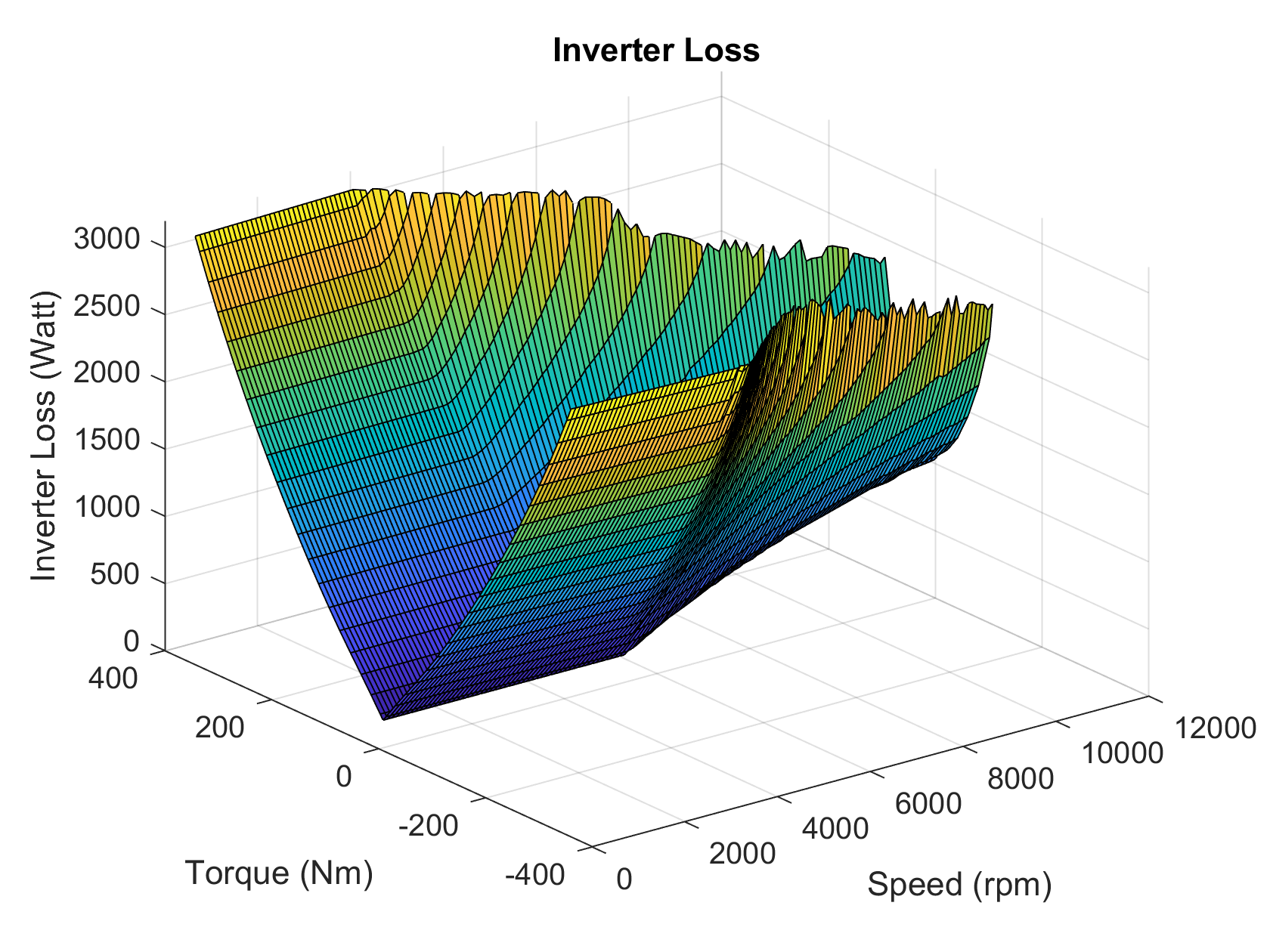
Inverter loss map · supplied document
Bring semiconductor losses into the drive model.
Extract device loss characteristics from datasheets and incorporate inverter losses into propulsion-system simulation.
Explore →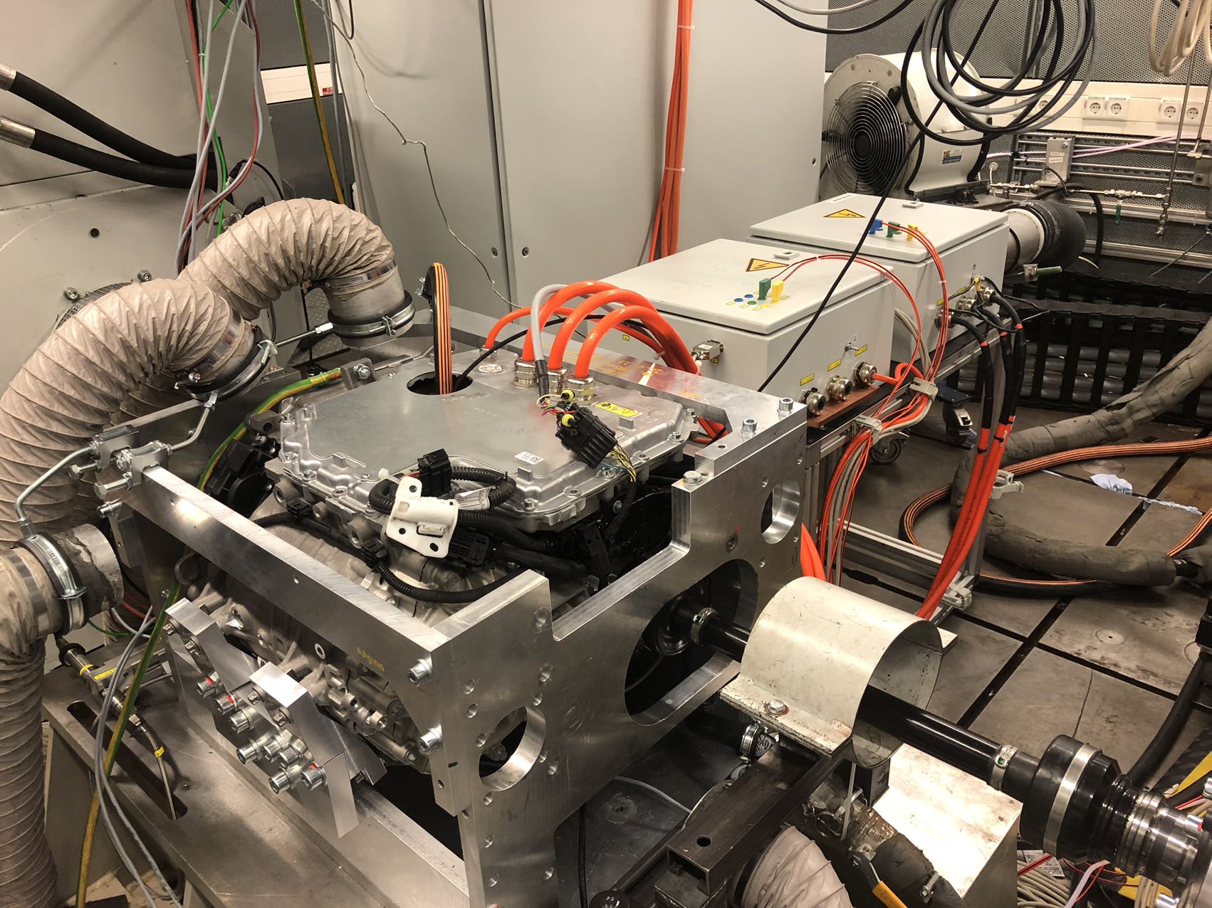
EESM test setup · supplied document
Externally Excited Synchronous Motor
Parameter identification and nonlinear modeling for an initially undocumented production machine.
Explore →Bring us your challenge.
Start with your application, constraints and the decision you need to make.