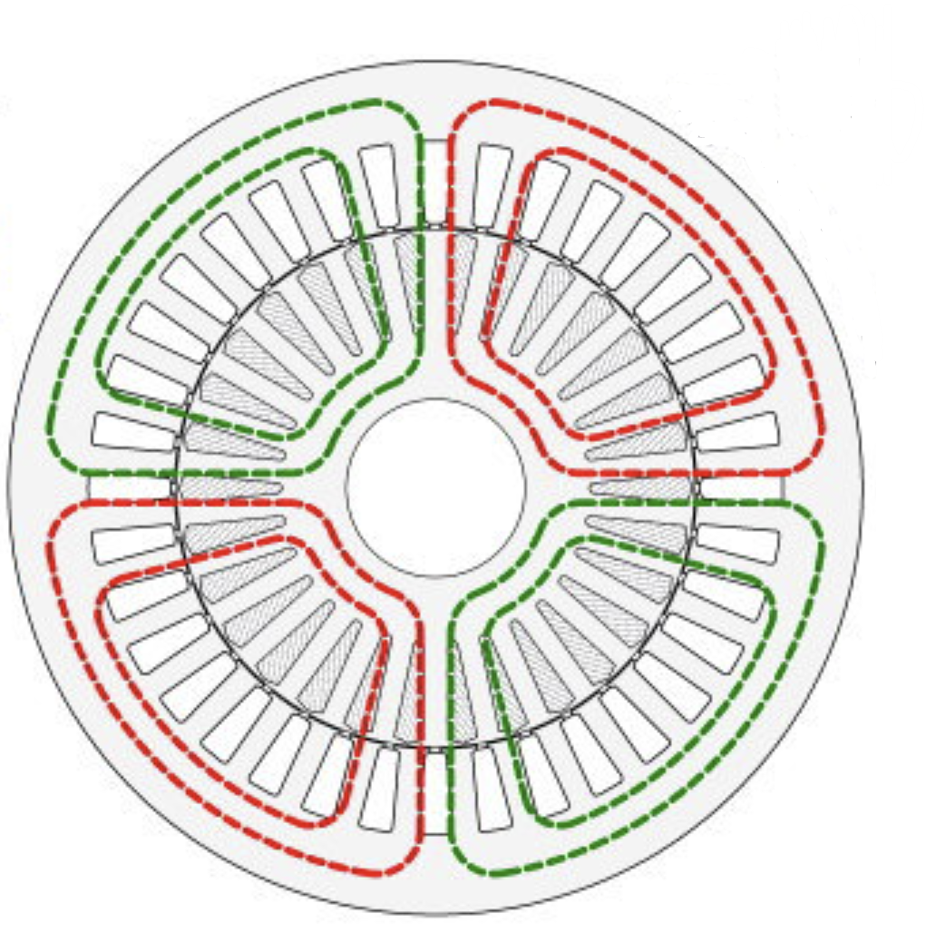
Two inverters, one open-winding machine
The supplied configuration used a 5 hp, 60 Hz, 230/460 V induction motor. A main inverter with a fixed DC input connected to one end of the open winding; a secondary inverter with a floating DC capacitor connected to the other end.
Manage floating-capacitor energy
The document describes the main inverter supplying real power and the secondary inverter supplying reactive power. Without appropriate control, the floating capacitor could experience a damaging voltage rise.
Model energy balance and prototype control
MATLAB/Simulink modeling investigated an energy-balance control approach, followed by implementation in a dSPACE prototype controller. The source reports a five-level line-to-line motor voltage and a constant-slip operating strategy intended to reduce motor losses.
Separate demonstrated behavior from longer-term benefits
The supplied video accompanies the reported prototype. The document provides no numerical efficiency gain, winding-temperature reduction or lifetime test; consequently, extended service life is not presented as an established result.
Explore the source material.
Video link supplied in the company document; not independently reviewed for technical performance.
Project description and outcomes are self-reported in the supplied company document. Linked video material is provided as a source reference, not independent verification or a customer endorsement.
Connected expertise.
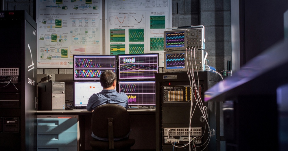
Hardware-in-the-loop test setup · supplied document
From offline simulation to real-time HIL.
Develop propulsion-system models in MATLAB/Simulink and bring machine and controller behavior into real-time testing.
Explore →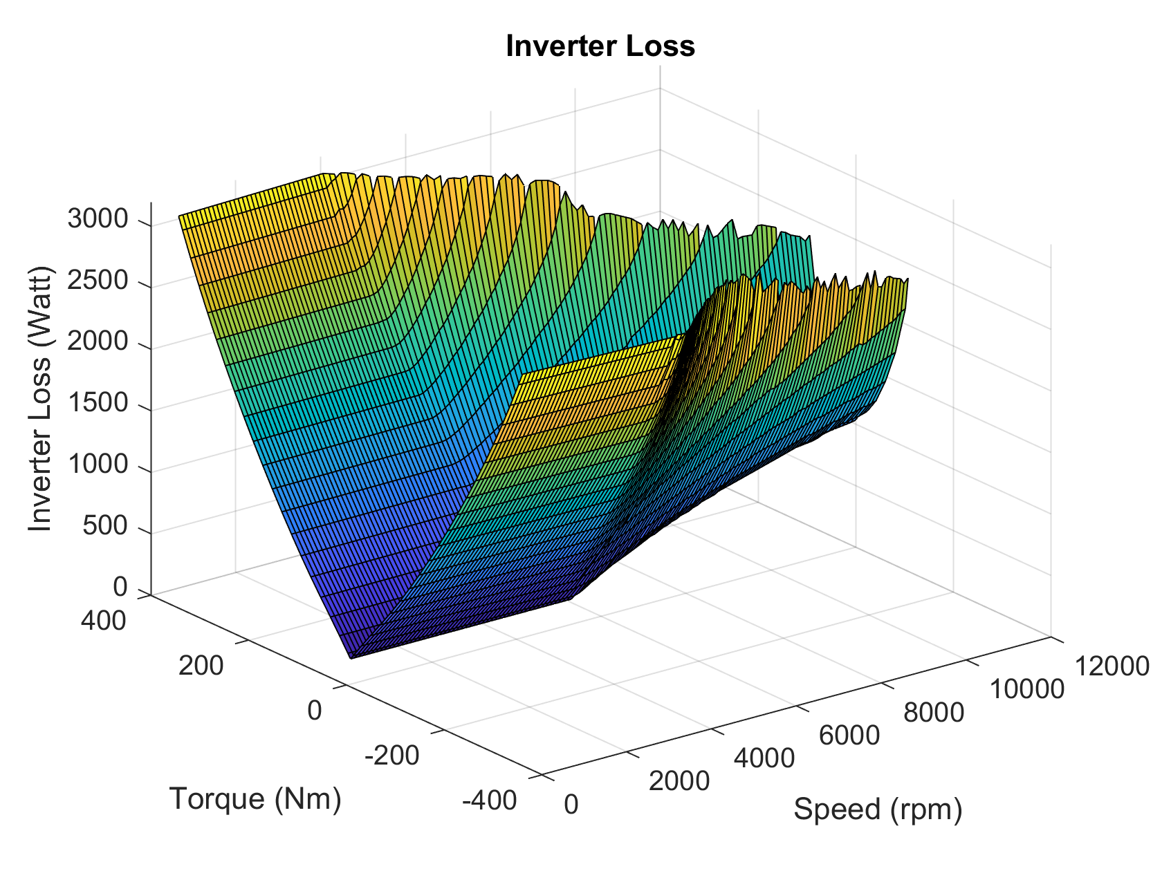
Inverter loss map · supplied document
Bring semiconductor losses into the drive model.
Extract device loss characteristics from datasheets and incorporate inverter losses into propulsion-system simulation.
Explore →Bring us your challenge.
Start with your application, constraints and the decision you need to make.